ANKO AS
TALLERES NAVALES PESQUEROS, S.A.
(NAPESCA/CCB ZAMAKONA)
Muelle Reina Sofía, Área V, Parcela C-26
Dársena Exterior, Puerto de Las Palmas (La Luz Port),
35008 Las Palmas de Gran Canaria – SPAIN
Anders Dalehaug
Department Manager in Spain
 | | ad@anko.no
|
|
 | | (+47) 48130992 | | | |
|
|
Contact
Ronni Holden
CEO
| | rh@anko.no
|
| | (+47) 41216053
|
Anders Dalehaug
Vessel Operations
| | ad@anko.no
|
| | (+47) 48130992
|
Odd Rune Olden
Business Development
| | oro@anko.no
|
| | (+47) 948 30 058
|
Headquarters Anko AS
Luramyrveien 12
4313 Sandnes
Norway
ANKO AS | +47 948 30 058 | Luramyrveien 12 | 4313 Sandnes | Norway | www.anko.no
|
Dimensional Survey Company
|
Services
 | | Anko AS was founded in 2016 by experienced engineers, each a specialist within different segments of the |
| | survey business. Even though Anko Bluepix is a young company – Our Mother company Anko AS was
|
established back in 1975. Anko Bluepix has a broad in-house survey competence with the goal to be a one-
stop shop for our clients. Together we will find a survey method that gives you the best results within your
specifications such as accuracy, time efficiency and price.
| | As-built survey of any structure
|
| | Navigation system control (Heading, Pitch and Roll)
|
| | DGNSS Health Check
|
| | ROV survey
|
| | Vessel survey
|
| | Rig survey
|
| | BlueEye – Subsea Photogrammetry
|
| | Offshore Installation
|
| | Offshore Windmills
|
| | Subsea structure offset survey and Calibration
|
| | High precision measurements
|
| | Reel survey
|
| | Survey Support during Multibeams installation
|
| | 3D Laser scanning
|
| | Establish Global Coordinate points
|
| | Survey management and consultancy
|
| | Development of special survey solutions for your projects
|
| | Drone Survey |
| | |
Vessel
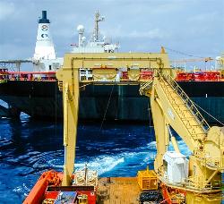
| | On a vessel it is a great advantage to know the as-built and as-installed position and alignment of all items |
| | utilized for operating the vessel. For some items it is even a necessity.
|
| | Such items might be Cranes, Moon Pool, Tower, Launch Systems, inclination of helideck, structures on |
| | deck, Taut Wires, etc.etc. Others are the positioning/navigation systems sensors like Antennae, Motion
sensors and sensors at the underside of the vessel like HPR poles and Multi Beams as well as other
transducers/transponders.
|
| | In order to know the position and alignment angles of all items in relationship to each other, one common |
| | coordinate reference system must be established on board the vessel. This is a local system made by one
axis pointing forward, along or parallel to vessel centerline, one axis pointing towards starboard, one axis
pointing upwards, a defined zero-point (CRP, coordinate/common reference point) and a defined reference
plane. The three axis are 90 degrees to each other. The CRP can be anywhere but it should be located on
a point which enable it to be picked out from the GA drawing of the vessel. The reference plane can be the
best fit plane on main deck or a plane best fitted through the draft marks on the hull. The reference system
should also be secured for future use by markers on the main structure.
|
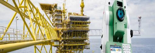
| | By means of a Totalstation, the offsets and installation angles of each item can be measured and tied into |
| | the coordinate reference system in order to have all positions and angles related to each other.
|
| | Finally, a written report consisting of descriptions, definitions, procedure, photos and coordinated |
| | tabular/sketches of all points of interest should be issued.
|
| | Survey by use of Totalstation is a cost- and time efficient solution to your specific needs. |
| | |
ROV
| | On a ROV it is very much the same principles as on a vessel, but it is often the main framethat is used as |
| | axis and plane reference. Some multi purpose ROV’s have survey frames that are mounted and dismounted,
then all axis and plane references are located to this particular frame.
|
| | By means of a Totalstation, the offsets and installation angles of each item can be measured and tied into |
| | the coordinate reference system in order to have all positions and angles related to each other.
|
| | Finally, a written report consisting of descriptions, definitions, procedure, photos and coordinated |
| | tabular/sketches of all points of interest are issued.
|
Rigs and Drillships
| | For Drillships it is very much the same principles and survey tasks as for other vessels.
|
| | For Rigs it is normally the centre lines between the corner columns that are used for establishing the |
| | reference axis. Centre turntable (centre well) is often used as CRP.
|
| | For both, the most commonly surveyed items in addition to the DP systems sensors is the drilling system. |
| | This is often position and alignment of the BOP in storage/resting location as well as the drilling system
consisting of guide rails and drilling machinery, dolly etc.
|
| | A typical survey job is therefore to measure and determine the guide rails straightness and the drill string |
| | alignment between top drive or crown block and centre turntable on drill floor.
|
| | Out of straightness of each guide rail relative to each other as well as out of theoretical dimensions between |
| | the rails is mapped. Then adjustments are carried out by the rig personnel and afterwards a new alignment
survey is performed in order to verify correct adjustments.
|
Navigation System Control
The main purpose with Navigation System Control is to check that the sensors are in good working order. That
there are no “drift” in the sensors. That the software input is correct and to adjust for the installation angles.
Vessel
With our specially designed software we can control all Attitude sensors and Gyro compasses. Our personnel have
many years experience with this work. This is a safe way to control that the right installation angles (C-O values)
has been entered into the software and that the different sensors show the same output value. Anko Bluepix will
install their equipment onboard the vessel and survey them into the local coordinate reference system. If there is
no system onboard Anko Bluepix will establish a new system. Static calibration is preformed at quay side with
simultaneously logging of Anko Bluepix and vessel systems. From these loggings a C-O will be calculated. A
verification is performed after the values has be put into the vessel system, to verify that everything has been
done correctly. Anko Bluepix also offers Dynamic calibration. This is a calibration preformed at open sea. If the
client has a tight time schedule we can perform the calibration while in transit.
ROV
When a new sensor is installed on the ROV the sensor is surveyed
to get the position and the installations angles. To verify the
function of the sensor a navigation system control should be
performed. The most preferred procedure is to set the ROV on land,
let the sensors stabilize and start simultaneously logging of Anko Bluepix
and ROV systems. C-O can be calculated and entered into the software.
Subsea Structure
When a Subsea structure is installed subsea, there are often sensors mounted on the structure itself to control the
operation. Checking the sensors before load out will document that everything is in order before the operation
starts.
Subsea Structures
The main reason for survey of subsea structures prior to load out is to get a complete documentation of the
overall construction and items on the structure
Important tasks that Anko Bluepix can assist with:
| | A third party control on as-built
|
| | Connect every sensor and installation piece into one common coordinate reference system
|
| | Install and survey Photogrammetry markers , so the structure is ready to be surveyed subsea
|
| | Document that vital installation pieces such as Guide pins, Guide Funnels and Landing Pads are correctly |
| | mounted
|
| | Measure Installation angles on each sensor so they all refer to the same centerline and reference plane |
| | (common coordinate reference system)
|
| | Perform a navigation system control on the sensors installed on the structure to document that the sensors |
| | are suitable for the installation work.
|
Underwater Photogrammetry
| | Subsea metrology using Close Range Photogrammetry, a well-proven method. Procedures and |
| | equipment have been designed uniquely to ensure easy subsea handling and reduce vessel time to a
minimum, without compromising safety and accuracy. The method can be used at any depth. We have
called our system BlueEye.
|
| | Point measurements can be performed with an accuracy of 1 to 10000 or better over lengths of more |
| | than 100 meters.
|
BlueEye can be applied for any structure where you want survey results, for instance:
| | Spool Metrology
|
| | Dimensions of small and large structures
|
| | Geometry of Jackets including nodes and legs
|
| | Pile survey
|
| | Guides and mini-posts
|
| | Dents and damages
|
| | Straightness, flatness and alignment surveys |
| | |
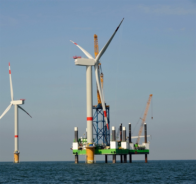
Offshore Windmills
| | Monopile installation
|
Anko Bluepix provide survey solutions with redundancy for positioning of vessel during monopole
installation. Our solution will give monopile position accuracy better than +/- 0.2m and continuous
monitoring of verticality during hammering with elevation accuracy +/- 0.1m. As-built documentation
delivered shortly after hammering.
| | Transition piece installation
|
Quick, safe and reliable installation of equipment on TP top prior to lifting. Gyro and/or GPS is used for
heading and motion monitoring during lifting and jacking. All with redundancy on heading and motion. Also
flatness survey of TP flange can be performed. Finally, As-built documentation will be provided.
| | Dimensional Control
|
As-built report | |
| | ad@anko.no
|
(+47) 48130992 |
| |
|